investigating a wifi security camera
dabbling in iot-sec for the first time 🥷🏻
while i am currently in the process of finishing my masters degree i saw that this semester there was a cybersecurity course being offered. i had taken this course in the past, back then it was a ‘hack the box’ / ctf kind of course. this of course means, that i cant use my participation in the course for my degree, if i do it its just for personal recreational reasons. i knew that this year the course would be managed by a different professor. out of curiosity i went to the first event and i got very pleasantly surprised.
this time the course was about embedded hacking, the two guys organizing the course had a background in networking and expected us to find vulnerabilitys by sniffing packets and going on from there. after the second session of the course some iot-devices were handed out. they were your run of the mill smart light bulbs, security cameras, smart door locks, a smart coffee machine, a smart fire alarm system etc. surprisingly these were mostly from household brands. not some aliexpress type devices where you would expect to find vulnerabilitys. among the products we got handed out there was even a phillips hue starter set.
in the past i have done some embedded engineering and i had been working in a physics lab for a brief time. i had not done embedded vulnerability research in the past but this seemed like a perfect opportunity. the course organizers assigned me a tp-link tapo c100 and i was more than happy to having a look at it.
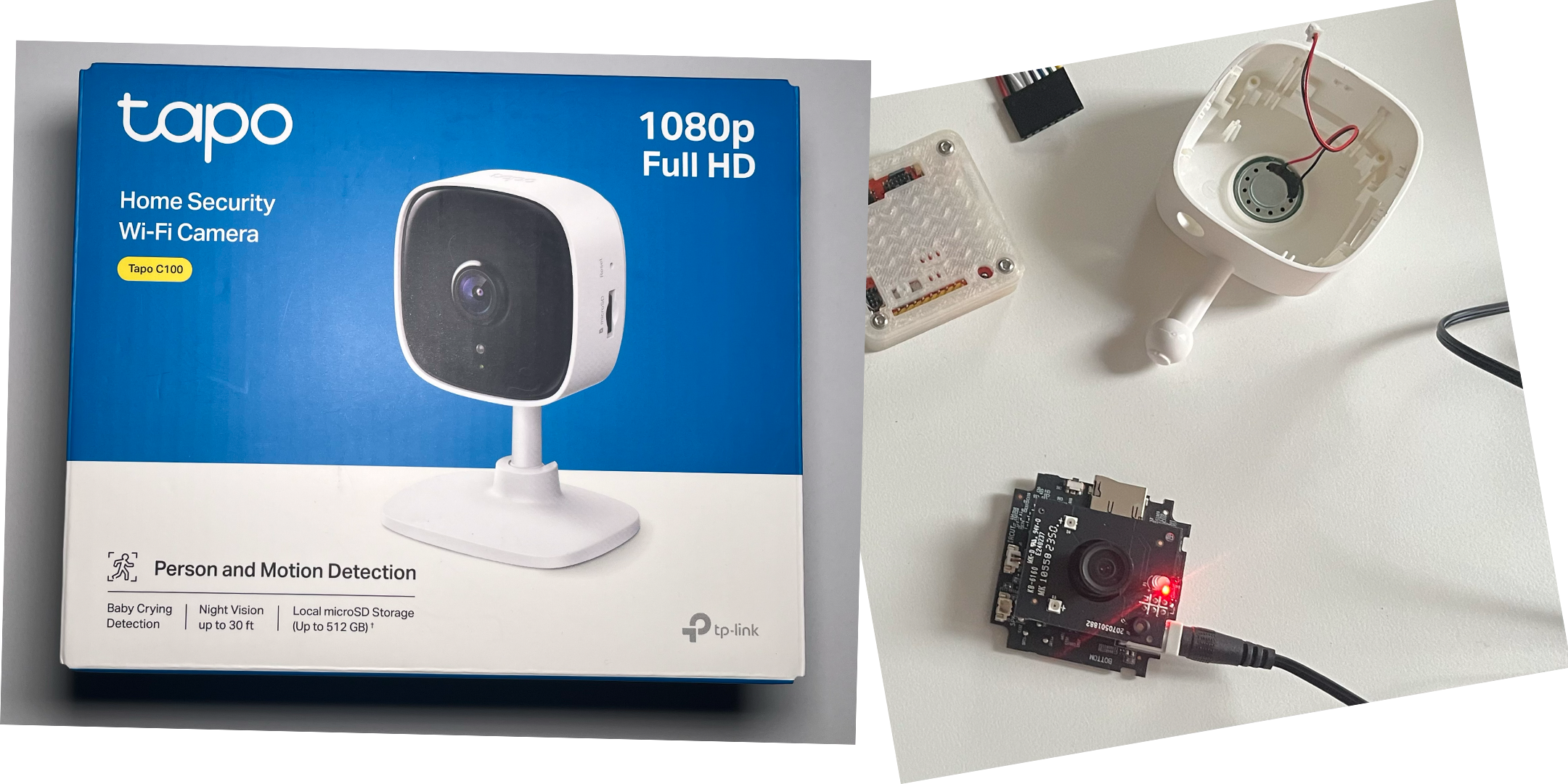
well, first thing i did was to remove the plastic shell to get to the pcb. this was really easy and can be done in a non destructive manner for this camera. the non destructive part was actually important to me as it is not my camera and i want to be able to return the camera to the course organisers so that future students can also have their fun with it 😉. I was looking for the usual uart pins on the pcb and low and behold they were very plainly placed right next to the largest chip on the board (as usual with the chip being the mcu).
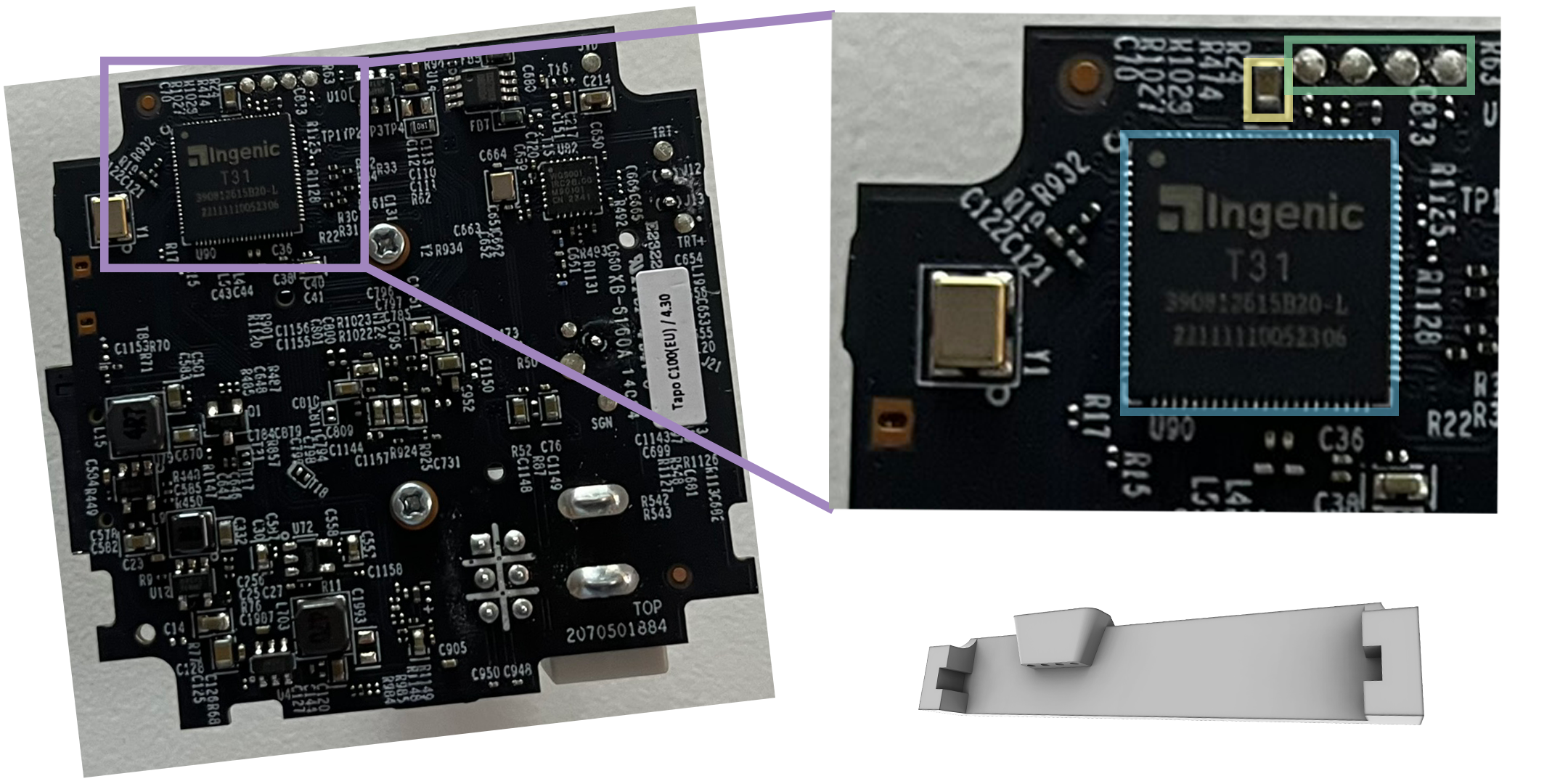
on the left is the entire pcb, on the right i zoomed in on the interesting part. there is the large chip (blue) but in this case it is actually the chip responsible for video processing. right above that there are 4 neatly aligned pads (green). looks like some uart to probe 😏. these pads are quite small, you can see the passive right next to it (yellow), this is a standard smd component in a 2.0 x 1.3mm package. each of those uart pads is about a millimeter in size. on the other hand my soldering iron is really cheap and lets say the steadines of my hands has a lot of room for improvement. i tried soldering some wires to those pads but the only thing i did was create a little mess. usually you would simply use probes for this but they are quite expensive, therefore i decided to model a little jig that i would mount in the corner of the pcb and place some standard breakboard wires in for probing (see the jig in the lower right corner of the picture). This also had the benefit of not soldering things to the board that was not acutally mine. after some jig iteration i printed it, connected it up to logic analyzer annnndddddd - nothing. using a multimeter i had found the power and ground pins in beforehand but the rx and tx pins were dead. thats really odd.
i looked up if there already was some info on the c100 uart out there and actually some people (see: VineethKumarM, james, io::pewpew(), related C200 by LassiHeikkila) had already done some hacking on a related camera which shared the same pcb. and indeed someone was able to connect to the camera via the same uart i was trying to connect to which actually even produced CVE-2023-49515. Therefore i assumed that tp-link may have disabled the uart connection completely after this had been disclosed in January of 2024. Either that or my probing jig needed some reworking 😅.
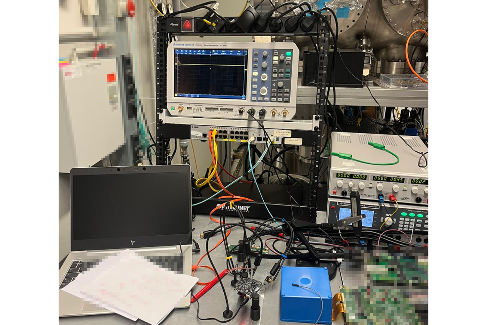
Funilly enough on the day that i had happened i met a friend who worked in the physics lab i talked earlier about and he invited me to stop by the lab and use their equipment to see if it my jig was the problem. some days later i took that oportunity and we met up in the lab. now with all the nice tools we probed the uart pins and indeed there was no signal. first i got a bit sad but then i decided to look more closely on to the uart pads and there it was. right in front of those pads there were unpopulated jumper pads. we only saw this under the microscope as these components are tiny (0.4 x 0.2 mm package size). if my theory was right, this meant that after the cve in january in tp-link decided to just not connect the uart pins anymore.
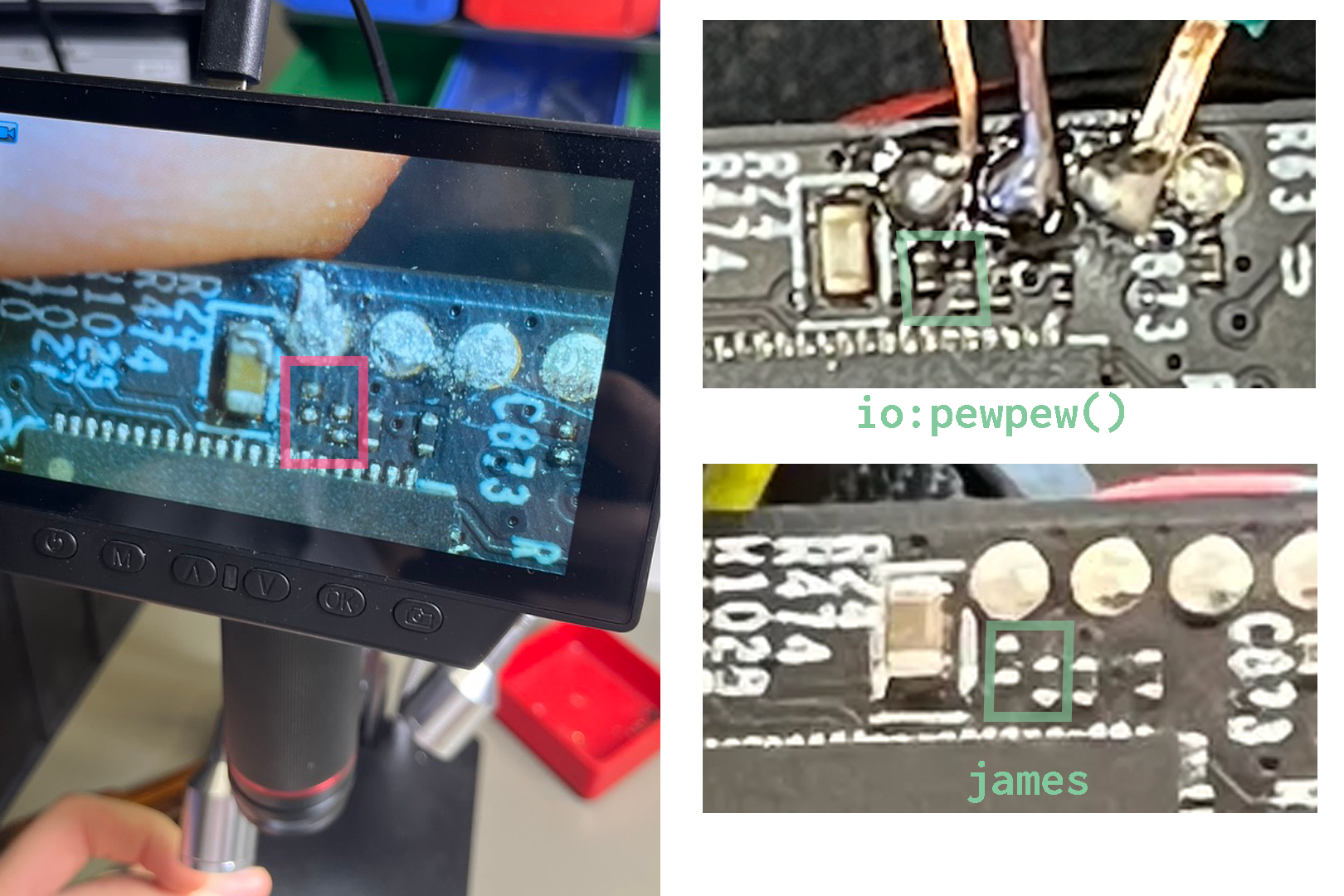
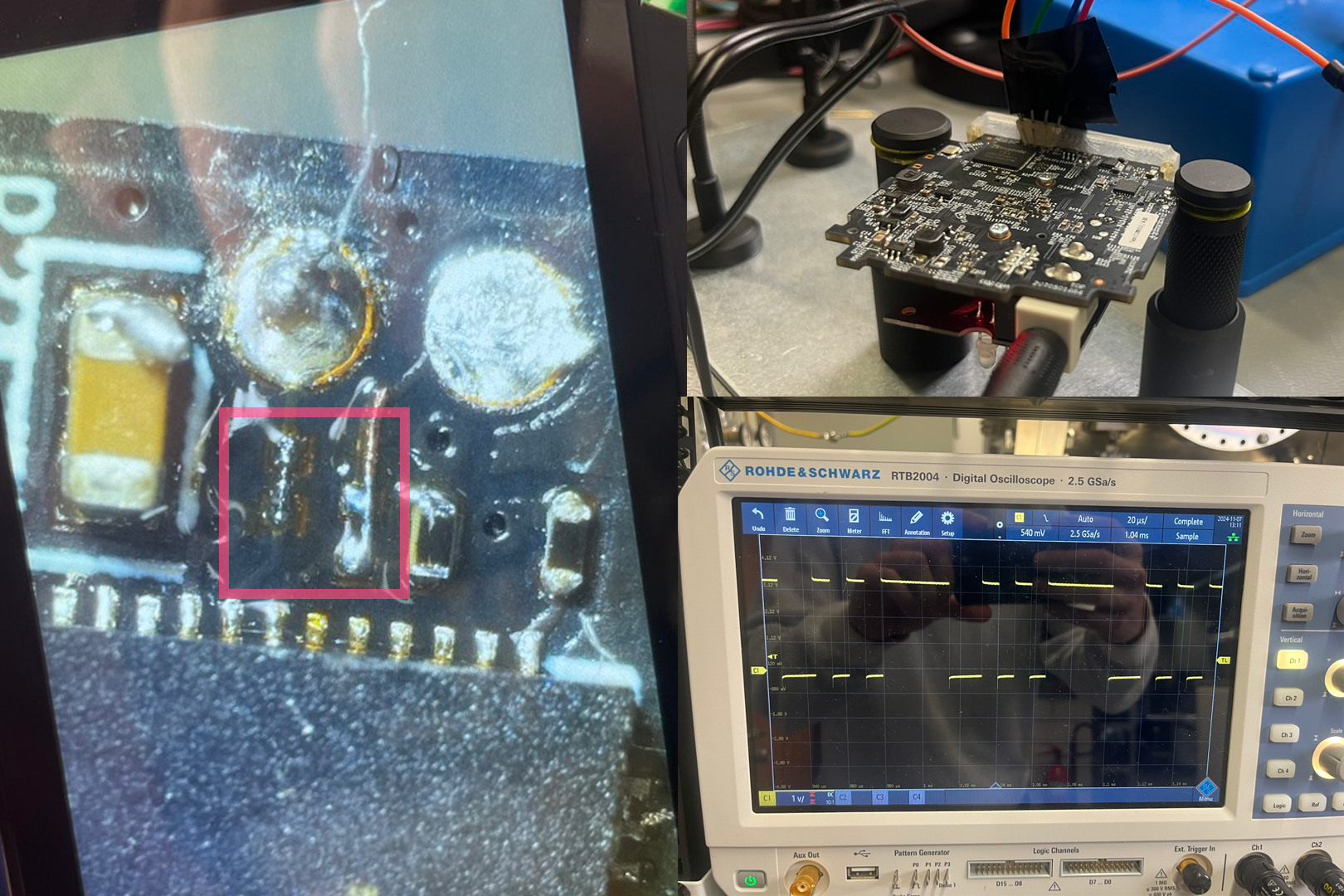
well, this theory had to be validated so my friend did some magic at the labs soldering station and shorted sub millimeter sized pads right next to the rx and tx pads. while he was doing that i looked up the pictures of the other people who had blogged about the tapo camera and indeed in their images of the pcb there was a jumper (on slide 2 see the green boxes vs my board on the right with the red box). when my friend was done (as can be seen on slide 3 in the red box, he did clean it up later and made it tidy but this was enough to short the jumps for now) we went back over to the oscilloscope and indeed there was a clean signal that looked very much like there were some bits to be captured. on the third slide you can also see the jig i had previously built to probe the ’large’ uart pads xd. this process had felt like a small adventure and seemed like looking behind the scenes of the tp-link engineering team.
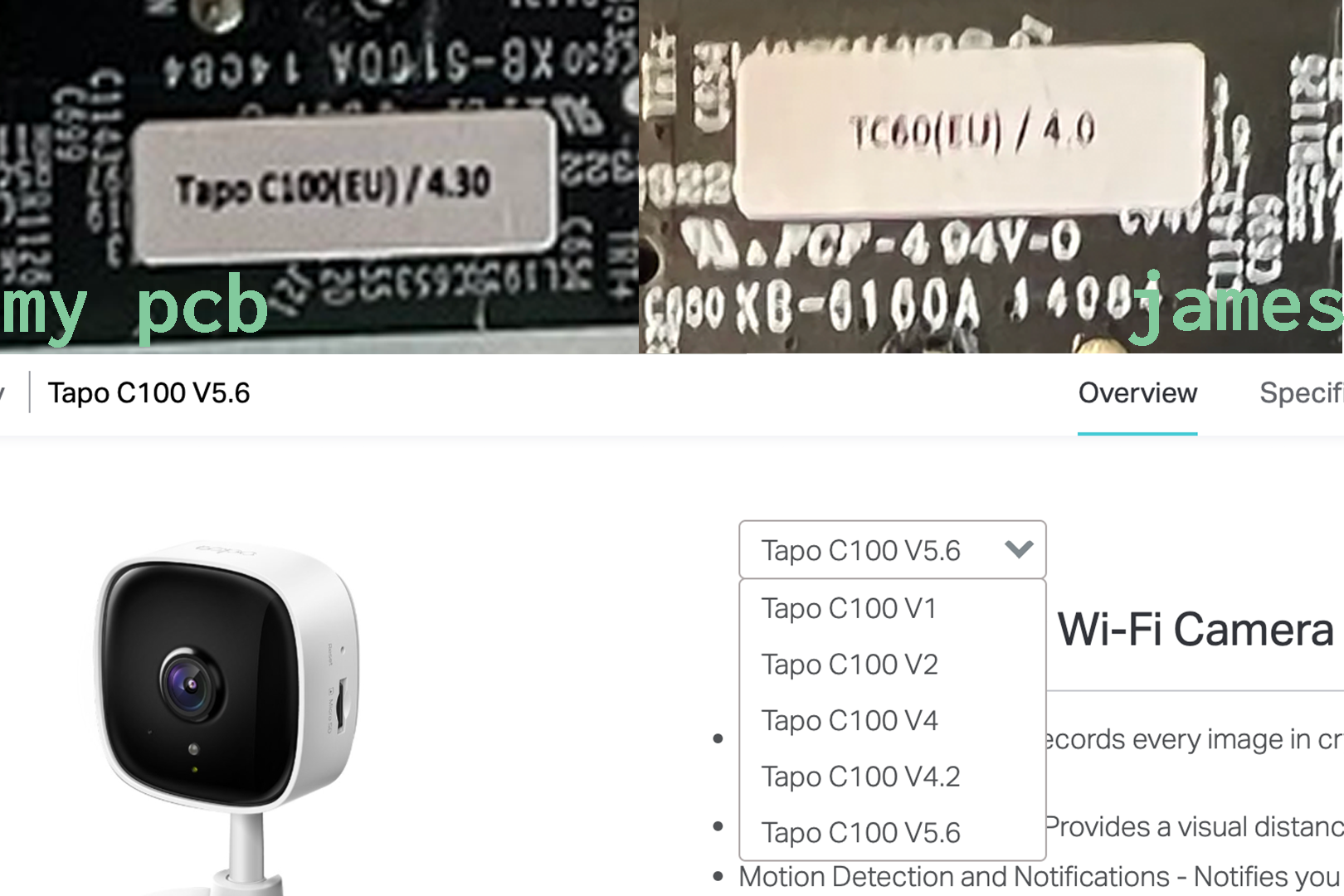
this means, that tp-link actually updated the pcb after the last cve had been published. you can even see this, the pcb has a version sticker. looking on to their website all of this looks even bleaker. there are a lot of versions of this camera. this makes working with this camera as a security researcher a bit exhausting as everything that has been found by other or that i find is not guaranteed to work on all c100 cameras. it almost seems like there are a dozen different c100 versions. besides the uart pads being disconnected in past versions of the camera there was a ethernet header on the pcb as can be seen here. this ethernet port was removed in my version and also the pcb traces to the location where this header was were completely removed.
well back to the board at hand. when i arrived home that day i tried connecting it to my logic analyzer and look if i would get some good data. lo and behold this looks very nice
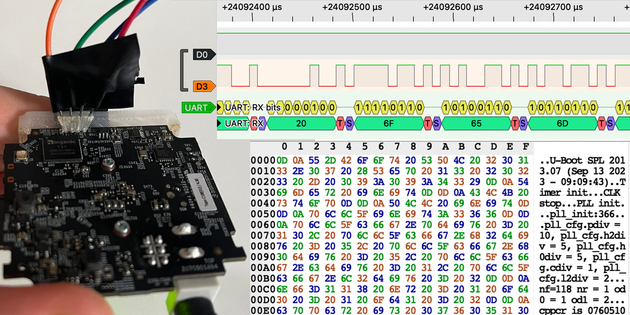
looks like a perfect uart connection, lets connect the tigard and see what can be done :)
[ 0.000000] Initializing cgroup subsys cpu
[ 0.000000] Initializing cgroup subsys cpuacct
[ 0.000000] Linux version 3.10.14__isvp_swan_1.0__ (root@smartlifeci1) (gcc version 4.7.2 (Ingenic r2.3.3 2016.12) ) #2 PREEMPT Wed Sep 13 09:30:16 CST 2023
[ 0.000000] bootconsole [early0] enabled
[ 0.000000] CPU0 RESET ERROR PC:9B056111
[ 0.000000] CPU0 revision is: 00d00100 (Ingenic Xburst)
[ 0.000000] FPU revision is: 00b70000
[ 0.000000] CCLK:1404MHz L2CLK:702Mhz H0CLK:250MHz H2CLK:250Mhz PCLK:125Mhz
[ 0.000000] Determined physical RAM map:
[ 0.000000]  memory: 00399000 @ 00010000 (usable)
[ 0.000000]  memory: 00037000 @ 003a9000 (usable after init)
[ 0.000000] User-defined physical RAM map:
[ 0.000000]  memory: 02d00000 @ 00000000 (usable)
[ 0.000000] Zone ranges:
[ 0.000000]   Normal   [mem 0x00000000-0x02cfffff]
[ 0.000000] Movable zone start for each node
[ 0.000000] Early memory node ranges
[ 0.000000]   node   0: [mem 0x00000000-0x02cfffff]
[ 0.000000] Primary instruction cache 32kB, 8-way, VIPT, linesize 32 bytes.
and we got a boot log, thats a win for now but it seems like it is a read only shell.
EDIT (19.01.25): this project got stale, the hardware was provided by my university and although the course is a semester long they wanted the hardware back after a week 🤷🏻♂️. altEventhough this blogpost is no way nearear completion i will keep it online as i could imagine it to be helpful to anyone tinkering around with the tp-link tapo line of cameras in the future.