Starting my Homelab
building a kilowatt 💡 on a budget 💸
abstract: how i built a mini rack with 5 hosts, a nas, gpu compute, 10g networking, remote management and much more from mostly second hand parts.
This has become a quite long homelab write-up. It mixes design intent, failures, measurements, and lessons learned. You can read it linearly, or jump between sections. for easier skipping around see this table of contents:
common wisdom in the community says homelabbing should start either with spare parts at home or with a cheap second-hand hp/dell/thinkcentre workstation. i wanted something a bit more out of the ordinary.
I already have done my fair share of hosting minecraft servers on raspberry pi’s and distributed webhosting on old mac minis and thinkpads. I was ready for something new. What i wanted from my setup was:
- Large Storage Pool (mainly for videography)
- The ability to host numerous vm’s
- GPU compute (to run my research experiments)
- complete remote manageability
- low idle power (at least the ability)
- a >3 node cpu cluster (learning distributed, kubernetes, ceph …)
To set expectations clearly, this post does not aim to be:
- A step-by-step guide for recreating the setup. It is a write-up of unconventional design choices and how they perform in practice.
- A strict budget build. In absolute terms it is likely more expensive than a typical homelab, but the focus is on optimizing performance per euro, not minimizing spend.
- A production-first system. This homelab is primarily a learning environment, despite having proven very stable so far.
- A cost or capacity comparison. I will not list total build cost or total storage size, i dont want to participate in this kind of competitions online and will only mention pricing where it meaningfully informs price/performance trade-offs.
Initially, I considered consolidating everything (see requirements above) into a single host (EPYC 7702, 256GB RAM, …) and relying on virtualization. I quickly abandoned this idea, as it conflicted with my goals: idle power consumption would have been high, and older Rome-era EPYC cores (~2GHz) are poorly suited for my ML workloads. While I could experiment with distributed systems in a virtual environment, working with real, multi-node hardware provides more realistic constraints and failure modes.
At that point, I started looking into multi-node architectures. Around the same time, I was introduced to the idea of mini racks (10-inch / half-width racks), which pair well with the growing ecosystem of tiny/mini/micro nodes. The form factor was appealing from both a power and density perspective, but adapting it to my requirements would require non-trivial engineering work.
architecture at a glance

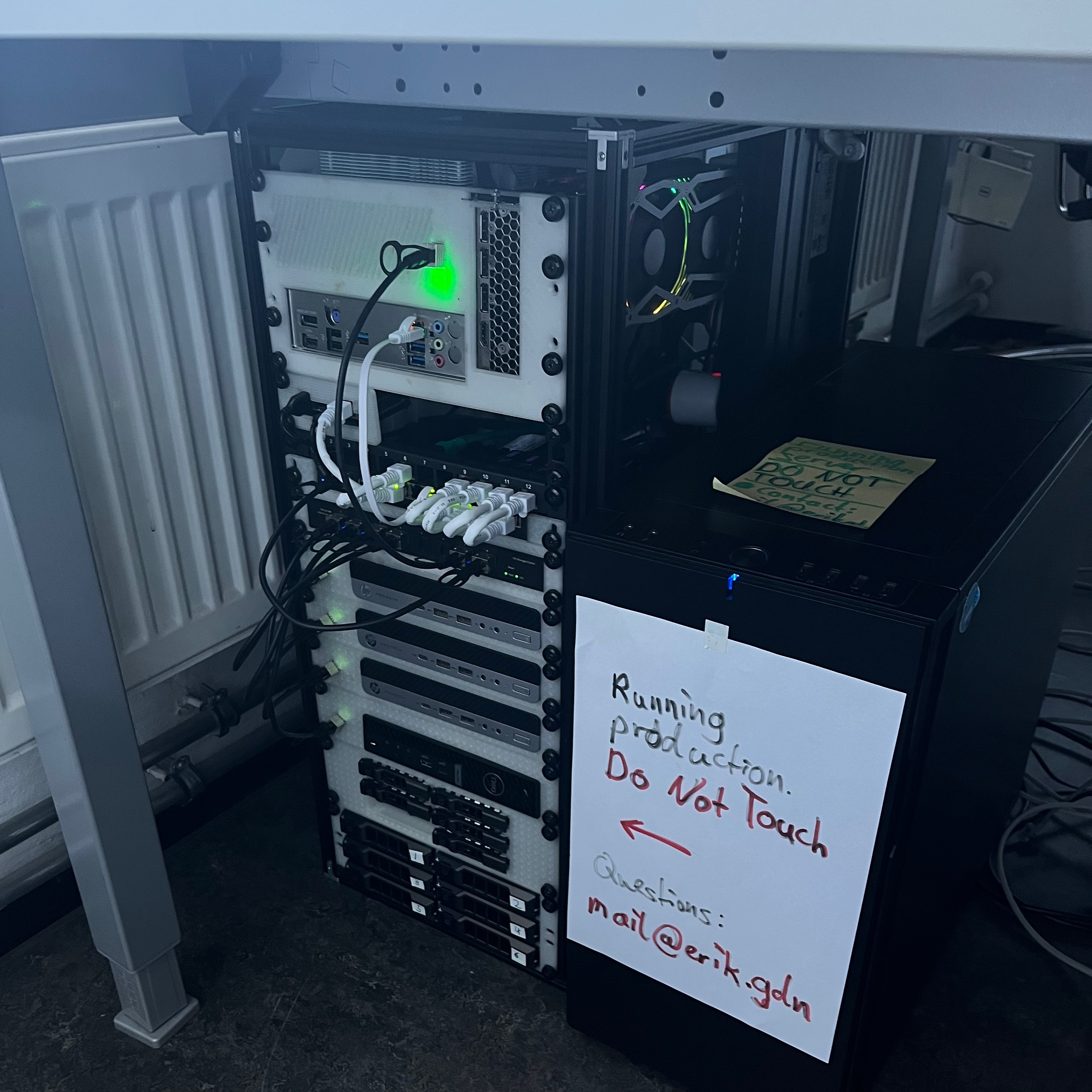
This homelab consists of five physical hosts housed in a 14U 10-inch rack and connected via a 10GbE SFP+ fabric. The cluster is intentionally heterogeneous: a dedicated GPU compute node for research workloads, a combined storage and virtualization node running Proxmox and TrueNAS, and a three-node CPU cluster used primarily for learning distributed systems. All nodes are remotely manageable and designed with aggressive power gating in mind, reaching close to 1kW under full load and targeting sub-30W idle consumption in the long term.
Nodes and Roles
- GPU compute node
Dedicated workstation-class host with an RTX 3090, used for research and long-running training workloads. - Storage / virtualization node
Proxmox host running a TrueNAS VM, responsible for bulk storage, VM hosting, and internal services. - CPU cluster (3 nodes)
Low-power mini PCs used as a sandbox for distributed systems (Ceph, Incus, Kubernetes). - Management plane
Out-of-band control via smart plugs (DIY PDU), PiKVM with KVM switch, and a dedicated WireGuard ingress.
Key Characteristics
- Form factor: 10″ / half-width rack (14U)
- Interconnect: 10GbE SFP+ (DAC)
- Peak power draw: ~700–1000W
- Current idle power: ~160W
- Target idle power: <30 (with future optimizations)
- Primary goals: GPU compute, storage, learning distributed systems
build
This section covers the hardware decisions i made for the cluster before any operational lessons: what I built, and why. I will start with the hardware itself and follow up later with my operational experience.
networking
tldr: 10G SFP+ is affordable and practical for homelabs, but PCIe lane allocation and NIC generation matter.
I started with networking, since it is the base layer everything else is built on. From previous distributed explorations of mine, it was clear that fast interconnects are essential for making a distributed setup both usable and enjoyable.
I knew I wanted at least 10GbE between nodes. An initial look at 10GbE over RJ45 quickly ruled it out: it was comparatively expensive, power-hungry, and known to run hot. SFP+ turned out to be the better alternative. While higher-end homelabs were already discussing migrations to 40g, 10GbE SFP+ had quietly become affordable for average homelabbers, in many cases costing roughly the same as 2.5GbE RJ45. This price drop was largely enabled by inexpensive managed 8-port 10GbE switches (for example this model) from Chinese vendors (around 80EU), as well as a workaround I found to enable 10GbE on tiny/mini/micro nodes.
A fundamental limitation of tiny/mini/micro systems is their lack of exposed PCIe slots (with the notable exception of some lenovo models), which normally makes adding high-speed NICs impossible. Instead, these systems rely almost exclusively on M.2 slots intended for NVMe SSDs.
To work around this, I used an adapter that converts an M.2 NVMe slot into a 10GbE SFP+ NIC by directly exposing the PCIe lanes of the M.2 interface.
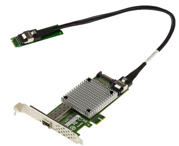
The adapter uses an Intel 82599 controller, is well supported by Linux, and costs around 10EU when purchased on sale. At that point, the experiment could begin.
Depending on the OEM motherboard design and CPU generation, M.2 slots may expose anywhere from PCIe3x1 (≈8 GT/s) up to PCIe5x4 (≈128 GT/s). Since NVMe SSDs typically use four lanes, most M.2 slots provide at least PCIex4 connectivity. With PCIe4 becoming standard around 2019, a single lane should, in theory, be sufficient for full 10GbE throughput (16 GT/s).
As later measurements show, this assumption does not necessarily hold when older NIC generations are involved.
The next step in the networking chain after the node NICs is a managed SFP+ switch, which I obtained for around 80EU. The model has been on the market for some time and is generally well regarded by homelab users. I still treat it as a black box and a potential security risk: while it is a layer-2 device and has no direct internet access, it can forward traffic for hosts that do. I have locked it down as far as possible and considered placing a packet broker in front of it, but in practice it is currently connected directly to the router. From a performance perspective, the switch has been entirely unproblematic and has never been the bottleneck, consistently sustaining full 10GbE throughput on multiple ports with small packets.
For routing and firewalling, I wanted something more feature-complete, both for reliability and as a learning platform. This led me to MikroTik, and specifically to the RB5009. It provides full RouterOS support, a 10GbE SFP+ port for the internal fabric, a 2.5GbE RJ45 uplink (which is sufficient given typical consumer uplinks in Germany), passive cooling, a compact half-width 0.5U form factor, and seven additional 1GbE ports that I primarily use for a management network.
To interconnect the SFP+ devices, I avoided fiber and transceiver modules in favor of direct attach copper (DAC) cables. For short runs, DACs are cheaper, consume less power, and are mechanically more robust than fiber. I paid around 7EU per 30cm cable. This approach is common in professional environments as well, including recent high-density GPU systems such as NVIDIAs nvl72.
update 21.01.2026: 4h after publishing this blogpost servethehome published an article on a new pcie4x1 realtek controller which fixes the exact issue described in this section (allbeit on rj45). This gives me hope that i will be able to solve this in the near future.
storage and vms
tldr: A single compact node combines virtualization and large-scale storage using heavily adapted M.2 slots and external JBODs.
I started this build with the goal of consolidating a growing archive of data (close to double-digit terabytes) that was previously spread across external USB drives. Reliability was a primary concern, which meant RAID from the outset and, in the longer term, adherence to the 3-2-1 rule backup rule once drive prices become more reasonable again.
Based on positive prior experience and community feedback, I decided to virtualize TrueNAS and combine storage and virtualization on a single node. This works well in practice: storage services require relatively little CPU time, allowing the system to host additional VMs efficiently. The approach does, however, require multiple SSDs (ideally separated for OS, VMs, and ZFS cache) and a generous amount of memory, as ZFS benefits significantly from RAM.
I therefore focused on tiny/mini/micro systems that offered a modern, high core-count CPU, multiple M.2 slots, and good availability on the used market.
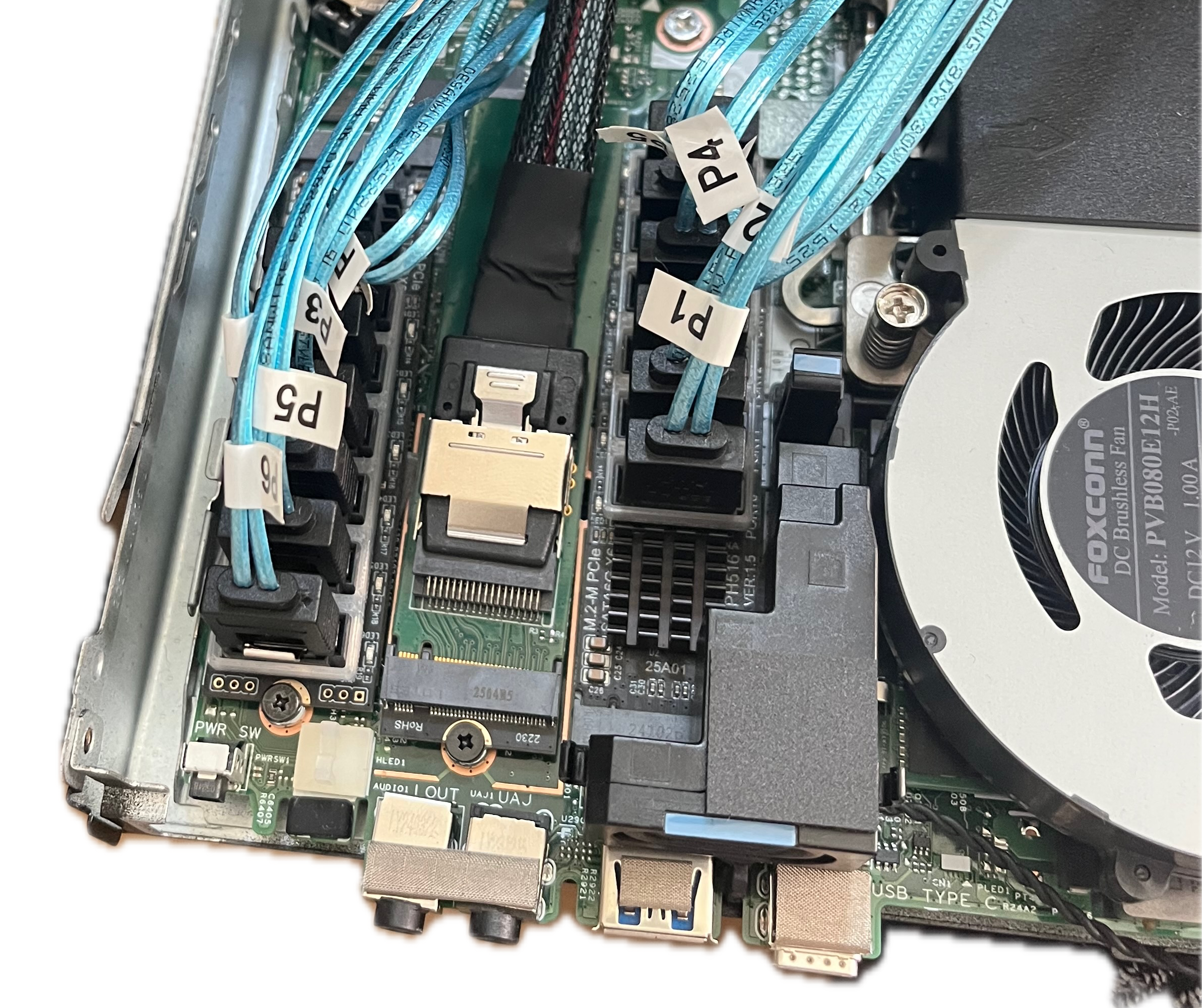
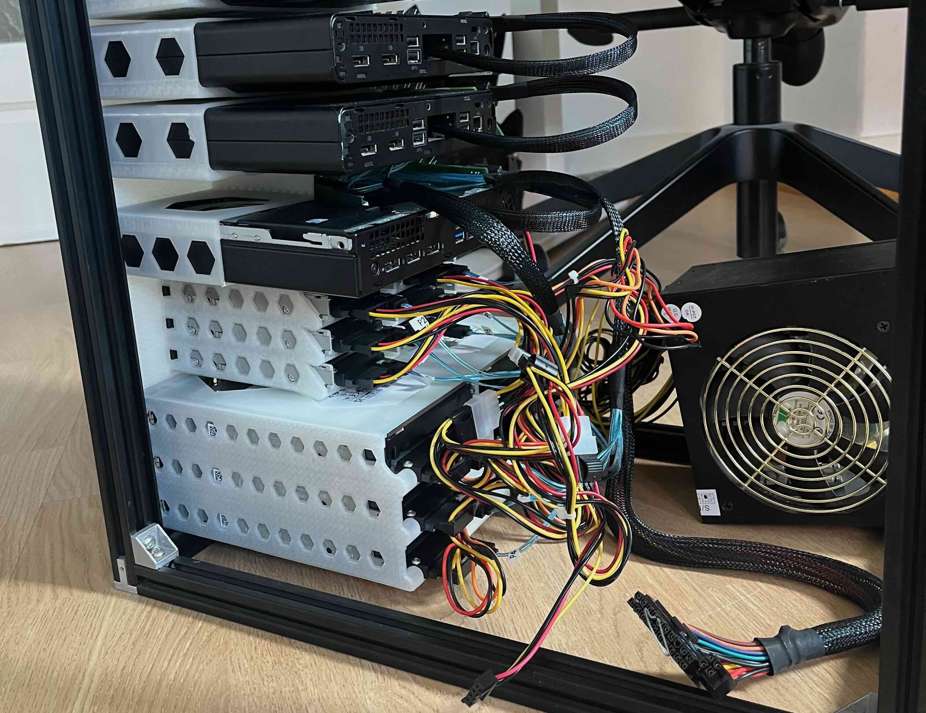
This led me to a dell optiplex 7020 micro plus, equipped with an Intel i5-14500 (14 cores, 20 threads) and 32GB of RAM, which I purchased used for under 300eu including shipping. Despite its compact size, the system provides two M.2 NVMe slots and a replaceable Wi-Fi card. Meeting the earlier requirements for 10GbE networking and multiple HDDs and SSDs is achieved through another unconventional adapter: an M.2-to-6SATA controller.
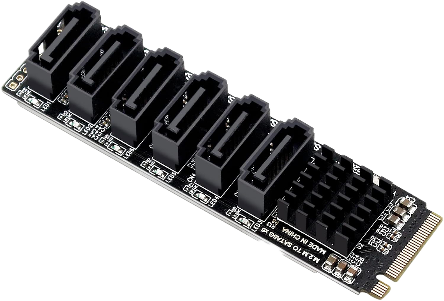
Instead of populating the system with two NVMe SSDs, I installed two M.2-to-6SATA controllers, providing a total of twelve SATA ports. I then repurposed the M.2 A/E-key slot (normally used for Wi-Fi) via an adapter to an M-key slot and connected the 10GbE NIC to it. The practical implications of this setup are discussed later in the operational experience.
To house the drives, I settled on a total of twelve bays: six 3.5-inch HDDs for bulk storage and six 2.5-inch SSDs for performance-sensitive tasks. One SSD is used as an ZFS L2ARC cache, two are mirrored as a ZFS special (metadata) vdev to improve lookup performance, two are dedicated to VM storage, and one bay remains unused. This required two external JBODs: one for the HDDs and one for the SSDs.
For the HDDs, I used a 3D-printable 10-inch 2U hot-swappable JBOD design that had already been validated by others with similar setups.

I paired this with Dell HDD caddies (15eu/6pc), a SATA backplane adapter, and a repurposed ATX power supply from an earlier build. Detailed assembly instructions for the original two-bay version are available in the referenced design, of which the six-bay variant is a remix.
Power delivery is a non-trivial challenge in this setup. While HDDs consume very little power when spun down (around 1–2 W per drive), spin-up currents can reach up to 25 W per drive. The current power supply is a temporary solution. Ideally, I would use a ~200 W PSU with peak efficiency at very low loads (around 8W), matching the system’s typical idle consumption. Such power supplies are effectively unavailable, so my long-term plan is to use an industrial-grade 12V PSU with strong low-load efficiency and adapt it for SATA power.
While I avoid detailed cost breakdowns, one reference point is useful: I purchased the HDDs new at 14.59eu/tb. Used enterprise drives are a viable alternative, but at the time I could not find a European supplier that met my requirements.
For the 2.5-inch SSDs, no suitable six-bay half-width JBOD was available, so I designed one myself with a height of 1.66 U. Dell enterprise 2.5-inch hot-swap caddies are used here as well. This leaves 1.33 U for mounting the Optiplex node itself, which is necessary to provide enough clearance for routing the twelve SATA cables. While the resulting layout does not conform to integer rack units and reduces portability, I treat it as a single 5U storage node rather than three independent components, which makes the compromise acceptable.
Finally, I added an SFP+ card mount to the node’s rack mount, allowing the DAC cables to be accessed from the front of the rack.
distributed cpu cluster
tldr: Cheap second-hand mini PCs make a low-risk playground for learning distributed systems without committing production workloads.
While sourcing parts for the GPU node, I spent a significant amount of time browsing second-hand markets and came across a deal that was difficult to ignore: a batch of HP ProDesk 600 G4 systems being sold at a steep discount. I purchased three units for 40EU each, each equipped with an Intel i5-8500T (6 cores, 6 threads), 16GB of DDR4 RAM, and a 256GB boot SSD.
These nodes offered an unusually strong price-to-performance ratio and were well suited as disposable, low-risk systems for experimentation. I had long wanted a dedicated environment for exploring distributed systems, and this cluster provided exactly that. After the systems arrived, I designed a custom rack mount for them, integrating the 10GbE NICs at the front, and installed them in the rack.

fun fact: with current pricing (jan 2026) the ram inside one of the nodes alone is worth more than double what i paid for the whole node.
rack building
tldr: building A DIY 10″ rack from aluminum extrusions is cheaper, deeper, and more flexible than off-the-shelf kits.
By the time the hardware came together, the rack itself was already assembled. As interest in mini racks has grown, commercial kits such as the DeskPi Rackmate have appeared on the market. At around 160 USD for 12U at a depth of only 26 cm, these options were both too expensive and too shallow for my needs. I therefore chose to build a custom rack using 2020 aluminum extrusions and 3D-printed parts.
For mounting, I used standard rack strips combined with brackets, spacers, and corner connectors to form a rigid extrusion frame. Using the interactive calculator below you can determine the correct extrusion lengths for a 14U rack at the desired depth.
output
| extrusion | count | length (mm) |
|---|
I strongly recommend using proper rack strips rather than mounting equipment directly to the extrusions. While the latter approach is simpler, it is not compliant with half-width rack standards. The issue is geometric: 2020 extrusions place mounting holes 10 mm from the edge, whereas the standard requires approximately 7.1 mm. This difference (~5.5mm less width) is enough to cause compatibility problems with designs that assume standard dimensions.
In practice, this matters. Some equipment fits very tightly (e.g. my switch) even in a standards-compliant rack and would not fit at all in a rack built directly from extrusions without rack strips.
In total, the 14U rack cage (including extrusions, rack strips, fasteners, and brackets) cost under 80eu and provides significantly more depth and flexibility than comparable off-the-shelf solutions.
management
tldr: Approximating Datacenter-style remote management cheaply using smart plugs, PiKVM, and careful orchestration works well.
With multiple nodes in the rack, I was missing several convenience features that are standard in datacenter environments, most notably baseboard management controllers (BMC) and remotely controllable power distribution units (PDU). My goal was to replicate the subset of these capabilities that mattered most to me (power cycling, power monitoring, out of band shell), using commodity hardware and open-source tooling.
I started with power management. In a datacenter, PDUs provide per-outlet power control and telemetry, which is essential for monitoring consumption and enforcing power gating. Commercial PDUs typically start at around 300 USD and offer numerous features I did not need for this setup. Instead, I built a DIY equivalent using a conventional power strip populated with Zigbee-enabled smart plugs, at a total cost of roughly 70EU.
In the smart home area smart power plugs with a similar feature-set are very common. this gave me the idea to simply buy a cheap powerstrip and some inexpensive off-the-shelf Zigbee smart plugs and fill the power strip with them. this cost me 70eu (60eu/8smart-plugs & 10eu power-strip)
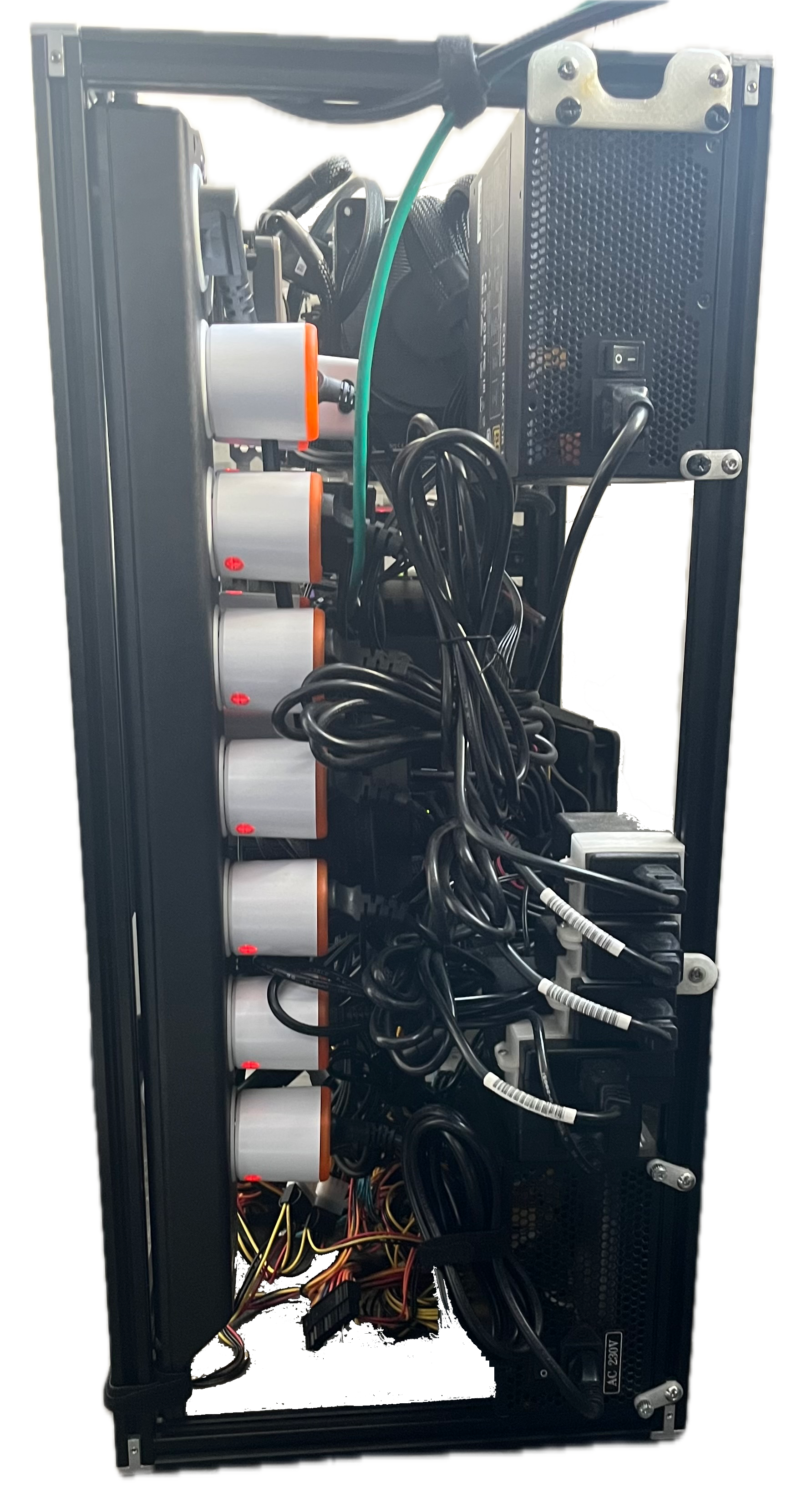
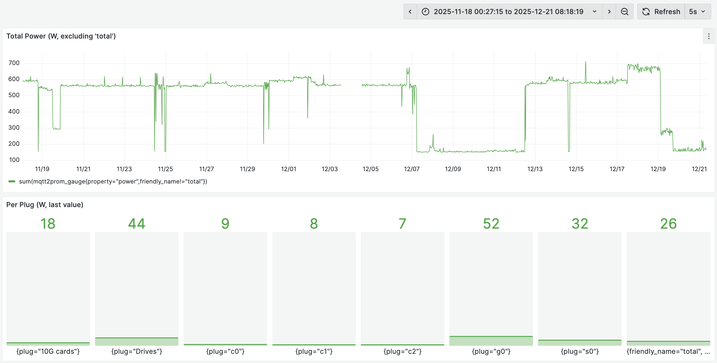
An Orange Pi Zero with a Zigbee USB adapter acts as the control plane. Using zigbee2mqtt, the plugs are integrated into MQTT, and power metrics are exported into Grafana for monitoring. Combined with BIOS support for automatic boot on power restoration, this setup allows for remote power cycling of individual nodes by simply cutting and restoring power. Significantly simpler than wiring GPIO-controlled power buttons on systems without front-panel headers.
To complete the remote management stack, I added an IP-KVM setup based on PiKVM. Since I needed console access for five hosts, deploying a dedicated Pi per node was not practical. Instead, I paired a single PiKVM instance with a multi-port KVM switch that supports serial control, allowing the active host to be selected remotely. A 10-port switch sourced for under 60eu was sufficient. The system was configured using the official PiKVM v2 documentation, with additional integration support from an existing open-source KVM-switch project.
gpu compute
tldr: building my own gpu compute capability in a cost-effective manner.
The research environment I operate in offers either aging GTX 1080 systems or a small number of shared high-end GPU nodes (EPYC platforms with A100 or V100 accelerators). While the latter look attractive on paper, they were chronically oversubscribed and operationally fragile: inconsistent driver stacks, missing security updates, sporadic kernel issues, and dozens of concurrent users competing for resources. In practice, this often made the newer hardware slower and less predictable than the older systems. At some point, I decided that having a reasonably modern, reliable, and fully controlled GPU node was worth the investment.
I opted for a workstation-style build based on a slightly older Intel platform. At the time, used Intel CPUs and motherboards from the previous two generations were readily available at favorable prices. I purchased an Intel 13700F with a compatible motherboard for 250EU, added 128GB of DDR5 memory, a 2TB PCIe4 NVMe SSD, and a 1kW power supply. This left only the GPU to be sourced.
I deliberately chose an NVIDIA card. While I evaluated AMD alternatives, driver maturity and ecosystem stability were critical requirements, and I needed a setup that would run experiments with minimal friction. After several weeks of monitoring the used market, I acquired an RTX 3090 locally for 550EU. Based on both compute/eu and vram/eu, it offered the best value at the time.
The GPU node has been running my thesis workloads almost continuously for several months. Despite the associated power draw, the system has proven reliable and predictable, which was the primary goal.

To integrate the system into the 10-inch rack, I designed and 3D-printed a custom case for the GPU node. While this required additional effort, standardized motherboard mounting and backplane dimensions made the process manageable and allowed the compute node to fit cleanly into the overall rack layout.
operational experience
After assembling the system, the next step was to put it into sustained use. While the applications in practice are discussed later, this section focuses on general observations from operating the homelab over several months.
power
tldr: The setup can pull close to 1kW under load, but with better power gating and ASPM could idle below 30W.
Power consumption is the most immediately noticeable characteristic of this setup. In its current state, idle power usage is high, but with targeted optimizations it is realistic to bring it below 30W, which would be entirely acceptable for a homelab of this size. At the moment, power efficiency has not been a top priority, partly because the system is hosted in a location with free of charge electricity and a symmetric gigabit uplink.
implement power on demand mechanisms
Only the WireGuard endpoint (running on an Orange Pi Zero) is strictly required for remote access. For latency reasons, the storage/VM node should also remain online, but the remaining systems can be powered off and booted on demand. Each CPU node idles at roughly 9W plus ~5W for its 10GbE NIC, and the GPU node idles at around 50W. Powering these down when idle would save approximately ~92W.nas spindown in idle
Drive spindown is not yet enabled, as it requires a firmware update for the ASM1166 M.2-to-SATA controllers and a more suitable power supply. HDDs currently consume around 7W per drive at idle. With spindown enabled and a PSU optimized for low-load efficiency, this could be reduced to roughly 2W per drive, lowering idle consumption from ~42W to ~12W.optimizing c-states
Further reducing idle power on the Proxmox/TrueNAS host requires enabling deeper CPU C-states. In theory, this could lower idle power from ~29W to around 15W (including the 10GbE NIC). However, the Intel 82599 NIC does not support ASPM, effectively limiting the system to C2 states. A more modern NIC, such as an Intel X710 adapted to M.2, would resolve this, but such options are rare. A PCIe X710 card is available for around 42EU and would amortize within roughly a year at German electricity prices.
Taken together, these changes would reduce the current idle power draw of approximately 160W to a best-case estimate of around ~25w.
Under load, the highest observed power draw so far has been roughly 700W, with about 600W attributable to the GPU compute node and the remainder coming from the rest of the rack at near-idle. In extreme scenarios, the rack can approach a total power draw close to 1kW.
Despite this range, the system has operated without any power-related issues over more than 5 months of continuous use.
networking
tldr: CPU nodes achieve full 10G line rate, while storage and GPU nodes are bottlenecked to 3.3g by PCIe2x1 limits of older NICs.
While setting up a Ceph cluster, I validated the interconnect performance between nodes. Traffic between CPU nodes reached stable, full 10GbE line rate without packet loss.
[nix-shell:~]$ iperf3 -c c1
Connecting to host c1, port 5203
[  5] local c0 port 49396 connected to c1 port 5203
[ ID] Interval           Transfer     Bitrate         Retr  Cwnd
[  5]   0.00-1.00   sec  1.10 GBytes  9.42 Gbits/sec   69   1.26 MBytes
[  5]   1.00-2.00   sec  1.10 GBytes  9.42 Gbits/sec    0   1.38 MBytes
[  5]   2.00-3.00   sec  1.09 GBytes  9.40 Gbits/sec    0   1.39 MBytes
[  5]   3.00-4.00   sec  1.10 GBytes  9.42 Gbits/sec    0   1.40 MBytes
[  5]   4.00-5.00   sec  1.10 GBytes  9.41 Gbits/sec    0   1.41 MBytes
[  5]   5.00-6.00   sec  1.10 GBytes  9.41 Gbits/sec    0   1.41 MBytes
[  5]   6.00-7.00   sec  1.10 GBytes  9.42 Gbits/sec    0   1.42 MBytes
[  5]   7.00-8.00   sec  1.10 GBytes  9.41 Gbits/sec    0   1.43 MBytes
[  5]   8.00-9.00   sec  1.10 GBytes  9.42 Gbits/sec    0   1.43 MBytes
[  5]   9.00-10.00  sec  1.10 GBytes  9.41 Gbits/sec    0   1.43 MBytes
- - - - - - - - - - - - - - - - - - - - - - - - -
[ ID] Interval           Transfer     Bitrate         Retr
[  5]   0.00-10.00  sec  11.0 GBytes  9.42 Gbits/sec   69            sender
[  5]   0.00-10.00  sec  11.0 GBytes  9.41 Gbits/sec                  receiver

iperf Done.
These results were consistent across longer runs and in both upload and download directions.
When testing connectivity between a CPU node (c0) and the storage/VM node (s0), the results were significantly worse:
[nix-shell:~]$ iperf3 -c s0
Connecting to host s0, port 5203
[  5] local c0 port 49114 connected to s0 port 5203
[ ID] Interval           Transfer     Bitrate         Retr  Cwnd
[  5]   0.00-1.00   sec   401 MBytes  3.36 Gbits/sec  106    406 KBytes
[  5]   1.00-2.00   sec   399 MBytes  3.35 Gbits/sec   49    332 KBytes
[  5]   2.00-3.00   sec   400 MBytes  3.35 Gbits/sec   17    317 KBytes
[  5]   3.00-4.00   sec   400 MBytes  3.36 Gbits/sec   23    361 KBytes
[  5]   4.00-5.00   sec   399 MBytes  3.35 Gbits/sec   14    431 KBytes
[  5]   5.00-6.00   sec   400 MBytes  3.35 Gbits/sec   22    332 KBytes
[  5]   6.00-7.00   sec   400 MBytes  3.35 Gbits/sec   15    410 KBytes
[  5]   7.00-8.00   sec   399 MBytes  3.35 Gbits/sec   51    414 KBytes
[  5]   8.00-9.00   sec   400 MBytes  3.35 Gbits/sec   18    409 KBytes
[  5]   9.00-10.00  sec   400 MBytes  3.35 Gbits/sec   21    379 KBytes
- - - - - - - - - - - - - - - - - - - - - - - - -
[ ID] Interval           Transfer     Bitrate         Retr
[  5]   0.00-10.00  sec  3.90 GBytes  3.35 Gbits/sec  336            sender
[  5]   0.00-10.00  sec  3.90 GBytes  3.35 Gbits/sec                  receiver

iperf Done.
At first glance, this was unexpected. The NIC in the storage node is connected via the Wi-Fi M.2 slot using an adapter, and I had previously verified that this slot exposes a PCIe4 lane, which should be more than sufficient for 10GbE. Inspecting the PCIe link, however, revealed that the connection was negotiated at PCIe2.
Further investigation showed that this was not caused by the adapter but by the NIC itself. According to the Intel 82599 datasheet, PCIe 2.0 is the newest standard supported by the controller. A single PCIe2 lane provides 5GT/s of raw bandwidth, which, after overhead, aligns closely with the observed ~3.3Gb/s throughput.
This explains the asymmetric behavior:
- On the CPU nodes, the NICs are installed in M.2 slots intended for NVMe SSDs, exposing four PCIe2 lanes (~20Gb/s raw), allowing full 10GbE throughput.
- On the storage and GPU nodes, the NICs are limited to a single PCIe lane via the Wi-Fi slot, resulting in the observed bottleneck.
One potential workaround would be to swap the PCIe lane allocation: move the NIC to the four-lane slot and place the ASM1166 SATA controller on a single lane. This would reduce disk bandwidth from ~14.5Gb/s to ~8Gb/s but increase network throughput from ~3.3Gb/s to ~9.4Gb/s, shifting the bottleneck accordingly.
In practice, most data in this setup is consumed locally by VMs before being served over the network, and ZFS scrubs would take significantly longer with reduced disk bandwidth. Combined with the additional complexity of double-adapting the M.2 interface, this trade-off was not worth it, and I kept the current configuration.
A future upgrade to a more modern NIC with PCIe4 and proper ASPM support would resolve both the bandwidth and power issues, but such cards are rare below 25GbE. As a result, this limitation may remain indefinitely.
I have not seen this PCIe-generation constraint discussed frequently in the context of Intel 82599-based homelab builds, and it is worth keeping in mind when budgeting PCIe lanes tightly.
management
tldr: Remote control works well, but iGPU passthrough, single ingress points, and KVM security remain improveable.
The management plane has proven reliable in practice. Power monitoring, remote power cycling, and console access via KVM all work as intended, and the setup has repeatedly allowed me to recover systems after misconfigurations or accidental network outages.
That said, several limitations became apparent during regular operation.
1. kvm without igpu: When passing the CPU’s integrated GPU through to a VM for hardware-accelerated video encoding or decoding, the host system loses its HDMI console. This is not an issue when a dedicated GPU is available, but in compact systems it effectively removes local console access to the hypervisor.
In this configuration, KVM access remains useful primarily during early boot and BIOS access after hard reboots. Once the accelerated VM starts, however, console access to the host is lost. Serial-over-LAN is often suggested as an alternative, but it does not help in scenarios where network connectivity itself is misconfigured, unless a dedicated management NIC is used.
This limitation only applies when the iGPU is fully passed through to a VM. In container-based setups, the iGPU can often be shared with the host retaining control, avoiding this issue entirely.
2. single entry point: All remote access currently depends on a single WireGuard endpoint hosted on an Orange Pi Zero. While this has been stable for several months, it represents a single point of failure and makes firewall changes unnecessarily stressful due to the risk of locking myself out.
To mitigate this, I plan to add a second, independent ingress node hosting a separate WireGuard instance. This is not intended to provide true high availability, but it would significantly reduce the risk of prolonged loss of access in the event of misconfiguration, especially when no physical access is available.
3. miscellaneous security considerations: i am very aware that there are numerous areas that still need improvement and that take time to setup. While SSH access to hosts is restricted to key-based authentication, this model does not extend cleanly to KVM-based console access. Keyboard/video interfaces inherently rely on local authentication mechanisms, which limits the ability to enforce strong, centralized access control. Using long, random passwords is possible but negatively impacts usability and day-to-day operations. This remains an unresolved area.
Additionally, secure boot is not yet enabled across all systems. Enabling it consistently in a heterogeneous environment introduces its own set of compatibility challenges, which I have not fully addressed yet.
overall
tldr: Despite its quirks, the cluster has been rock-solid, efficient enough, and pleasant to operate given its cost and complexity.
Overall, the system has been a pleasure to work with. It has run continuously for over 5 months with 100% uptime, and all hardware was recognized without issues on first boot. The only instability encountered was elevated PCIe latency on the M.2-adapted 10GbE NIC, which was resolved by reseating the adapters.
The inexpensive 10GbE switch has been entirely unproblematic and idles below 10 W. Likewise, the MikroTik RB5009 has been a good fit for this setup. While RouterOS can be opinionated, it works well when limited to routing and firewalling. Once configured, it has required little ongoing attention and offers strong value for its price.
applications in practice
tldr: The homelab is actively used for ML research, storage-heavy services, and experimental distributed systems.
A common question about homelabs (especially at this scale) is what they are actually used for. In this case, the system is actively utilized across all major components.
1. gpu compute
The GPU node is used extensively for research workloads. A minimal NixOS installation with project-specific flake-based development environments provides a clean and flexible setup, albeit with some added debugging overhead. Over the past four months, the GPU node has operated at over 500W for more than 60% of the time, primarily running image classification experiments. It handles ImageNet-1K training comfortably, which is near the upper bound of what I require. While the node was not inexpensive, it enables independent, reproducible research and provides guaranteed access to private compute resources.
2. storage node
The storage node runs Proxmox with a large TrueNAS VM managing the ASM1166 PCIe devices. In addition to storage, it hosts several small VMs running containerized services, separated for firewalling and isolation. These include internal infrastructure (e.g., DNS, metrics, dashboards), workers/scrapers, workflow tools, limited public services, and a typical media stack. The system remains underutilized in terms of CPU, while RAM usage is consistently high due to ZFS. This leaves ample headroom to expand services over time.
3. cpu compute cluster
The CPU cluster is used primarily as a learning environment. Given the low acquisition cost, it serves as a low-risk platform for experimenting with distributed systems. To date, I have deployed NixOS across the nodes, configured a Ceph cluster (with some friction, as documented in the nix-wiki), and experimented with Incus for high-availability VM hosting. Stability issues with the Incus daemon have postponed further work in that direction. A Kubernetes cluster is planned for future exploration. While this part of the homelab is the least essential operationally, it remains valuable as a hands-on learning platform.
Looking ahead, I would like to combine all components into a continuous learning pipeline: distributed data collection and preprocessing on the CPU nodes, intermediate storage on the storage node, model training on the GPU node, and inference served from a VM.
conclusion
tldr: While I wouldnt rebuild it at todays prices like this, the design choices, form factor, and learning outcomes remain absolutely worth it.
If I were to build a homelab today, I would not recreate this setup exactly. The primary reason is cost: with current RAM and storage pricing, an equivalent build would be roughly twice as expensive. In that sense, this system is very much a product of its timing.
Reframing the question about if i would rebuild the homelab the same way again. If we assume mid-2025 pricing, I would change surprisingly little. I would still avoid full-size rack or traditional enterprise hardware for economic reasons. High-speed networking, even at 10GbE (or effectively ~3.3Gb/s in some paths), has proven useful far more often than expected, particularly for file movement and distributed workloads. While ASPM-capable NICs remain on my wishlist, there are currently no practical options that integrate cleanly with M.2-based systems.
The storage setup, while unconventional, has been reliable and enjoyable to use, and having more capacity than I immediately need has been a meaningful quality-of-life improvement, especially for video work. The CPU cluster has justified itself as a learning platform, acquired at a price that makes experimentation low-risk. The remote management stack (smart plugs, PiKVM, and a KVM switch) has repeatedly paid for itself, particularly during periods when physical access was impossible. Finally, the 10-inch form factor strikes an effective balance between accommodating small, nonstandard hardware and maintaining a compact, structured system.
In the big picture, I am very satisfied with the result. The setup has its flaws, but given the money spent, the capabilities gained, and the amount learned along the way, it has more than met my expectations.